Bit Manipulation
Some examples to go through
- 0110 + 0110 = 0110 * 2 = shift 0110 to the left by 1 bit = 1100
- 0100 * 0011 = 4 * 0011 = shift 0011 to the left by 2 bits = 1100
- x XOR ~x = 1111
- ~0 << 2 = 1111 << 2 = 1100
Bit Tricks
|
|
|
Two's Complement & Negative Numbers
Computers store integers in two's complement.
Positive num => sign bit = 0 Negative num => sign bit = 1
Computers store integers in two's complement.
Positive num => sign bit = 0 Negative num => sign bit = 1
|
Ex1: 4-bit integer, (-3)
Set sign bit = 1, we are left with 3 remaining bits 2^3 = 8 => 8 - 3 = 5 => 5 in binary is 101 So (-3) in 4-bit integer is: 1 101 |
Ex2: 4-bit integer, (-7)
(+7) in 4-bit integer is 0 111 get its 1's complement which is its XOR = 1 000 2's complement = 1's complement + 1 = 1 001 So (-7) in 4-bit integer is: 1 001 |
|
~~ Positive Values ~~
|
~~ Negative Values ~~
|
Shifting Bits
Using these operations, given a number - we can get the ith bit, set the ith bit, and clear the ith bit
Application: given a num, it's faster to check if it's even or odd by just checking the least significant bit - if 1 => odd else even
* Shifting Arithmetic Right fills the right-side with the current sign bit 0/1
- Logical >>> ex: x >>>= 1 # Logical right shift by 1
- Arithmetic >> ex: x >>= 1 # Arithmetic right shift by 1
Using these operations, given a number - we can get the ith bit, set the ith bit, and clear the ith bit
Application: given a num, it's faster to check if it's even or odd by just checking the least significant bit - if 1 => odd else even
* Shifting Arithmetic Right fills the right-side with the current sign bit 0/1

Intro
|
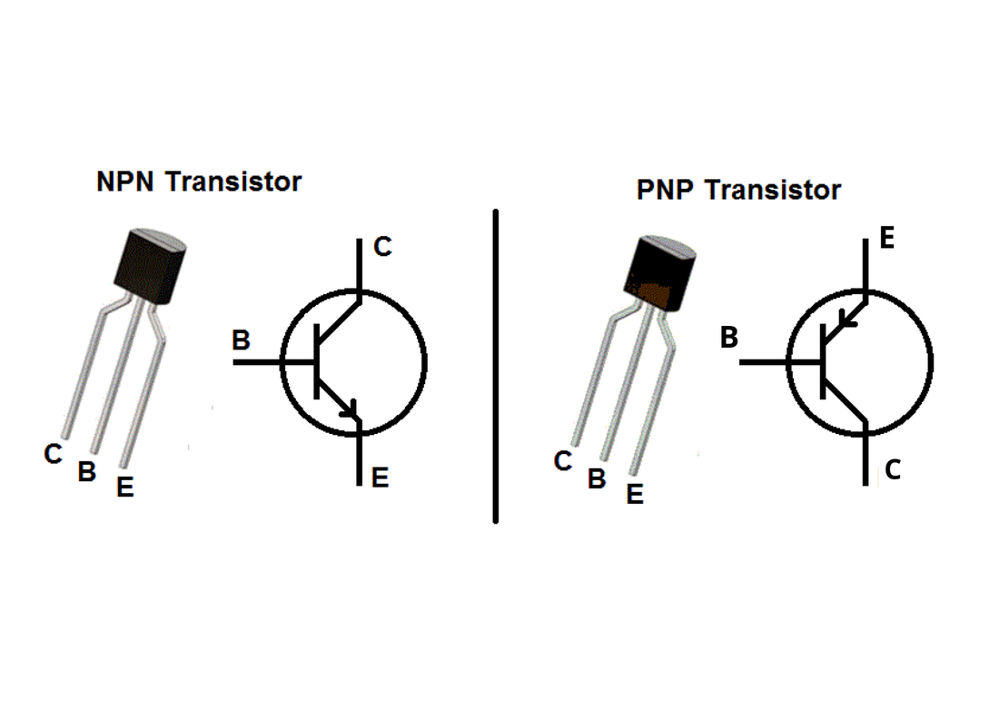
A transistor is a semiconductor device (usually silicone) used to amplify (ie: used for hearing aids, speaker, ...) or switch electrical signals (used for CPUs) and power. Each transistor can store 2 distinct states 0 and 1. Highly advanced transistors work by controlling the movements of an electron. A logic gate in a microchip is made up of a specific arrangement of (MOSFET) transistors.
|
|
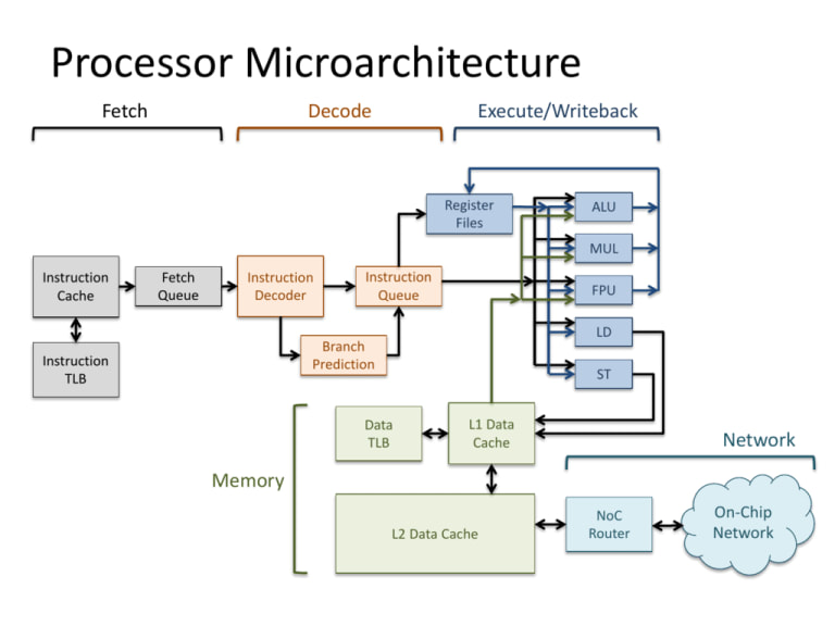
Computer Organization is the topic of how a processor is built to execute various instructions. It is primarily responsible for the following steps
1. Read an instruction and decode it
2. Find any related data that is needed to process the instruction
3. Process the instruction mainly using ALU
4. Write the results out to output register
1. Read an instruction and decode it
2. Find any related data that is needed to process the instruction
3. Process the instruction mainly using ALU
4. Write the results out to output register
8-Bit CPU
The 8-Bit CPU is a project that I worked on using a digital circuit simulator: Logisim. My objectives of the 8-Bit CPU project are as follows:
- Exhibit my understanding of circuits and how it is embedded in the functionality of a CPU
- Design the foundation of a computer processor so that it can be modified to build a complex processor for specific purposes
- Understand how programs are processed and how it can be optimized effectively
The processor in this project utilizes 8-bits and Complex Instruction Set Computers (CISC) instructions to generate the ROM content which will then be loaded into the instruction decoder circuit. All files related to this project can be viewed in my GitHub page here
I have provided a guide on how programs can be written and executed using my 8-Bit CPU. Below I provide details on the components of the CPU and how it is designed to function.
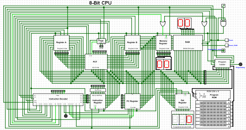
8-Bit CPU Explanation
Using the guide provided above and the op_code table, a program can be written in assembly and converted into a binary file. This binary file will be loaded onto the ROM Program. When the programming mode is turned and the clock ticks are enabled, the program loader reads the content from ROM and writes it into RAM. When the program is completely read from, the programming mode should be turned off. Now, the program execution begins. The databus connecting from RAM to all the other registers allow data to be read and stored accordingly. The PC register always contains the address of the next instruction, so the instruction decoder using the address fetches the next instruction from RAM, decodes it and changes the control flag for processor to execute the instruction. Any parameter values required for the instruction gets stored into register A and B respectively. Next, the ALU with the given flags and arguments, performs the execution and sends the result to the output register, which is decoded from 8-bit-to-7-segment display to conveniently view the output.
Using the guide provided above and the op_code table, a program can be written in assembly and converted into a binary file. This binary file will be loaded onto the ROM Program. When the programming mode is turned and the clock ticks are enabled, the program loader reads the content from ROM and writes it into RAM. When the program is completely read from, the programming mode should be turned off. Now, the program execution begins. The databus connecting from RAM to all the other registers allow data to be read and stored accordingly. The PC register always contains the address of the next instruction, so the instruction decoder using the address fetches the next instruction from RAM, decodes it and changes the control flag for processor to execute the instruction. Any parameter values required for the instruction gets stored into register A and B respectively. Next, the ALU with the given flags and arguments, performs the execution and sends the result to the output register, which is decoded from 8-bit-to-7-segment display to conveniently view the output.
- Accumulator:
This is the most frequently used register used to store data taken from memory. It is in different numbers in different microprocessors. - Memory Address Registers (MAR):
It holds the address of the location to be accessed from memory. MAR and MDR (Memory Data Register) together facilitate the communication of the CPU and the main memory. - Memory Data Registers (MDR):
It contains data to be written into or to be read out from the addressed location. - General Purpose Registers:
These are numbered as R0, R1, R2….Rn-1, and used to store temporary data during any ongoing operation. Its content can be accessed by assembly programming. Modern CPU architectures tends to use more GPR so that register-to-register addressing can be used more, which is comparatively faster than other addressing modes. - Program Counter (PC):
Program Counter (PC) is used to keep the track of execution of the program. It contains the memory address of the next instruction to be fetched. PC points to the address of the next instruction to be fetched from the main memory when the previous instruction has been successfully completed. Program Counter (PC) also functions to count the number of instructions. The incrementation of PC depends on the type of architecture being used. If we are using 32-bit architecture, the PC gets incremented by 4 every time to fetch the next instruction. - Instruction Register (IR):
The IR holds the instruction which is just about to be executed. The instruction from PC is fetched and stored in IR. - Pipelining: the process of collecting instruction from the processor through a pipeline. It stores and executes instructions in an orderly process - As soon as the instruction in placed in IR, the CPU starts executing the instruction and the PC points to the next instruction to be executed. - Condition code register ( CCR ) :
Condition code registers contain different flags that indicate the status of any operation.for instance lets suppose an operation caused creation of a negative result or zero, then these flags are set high accordingly.and the flags are
- Carry C: Set to 1 if an add operation produces a carry or a subtract operation produces a borrow; otherwise cleared to 0.
- Overflow V: Useful only during operations on signed integers.
- Zero Z: Set to 1 if the result is 0, otherwise cleared to 0.
- Negate N: Meaningful only in signed number operations. Set to 1 if a negative result is produced.
- Extend X: Functions as a carry for multiple precision arithmetic operations.
So, these are the different registers which are operating for a specific purpose.
Full Adder
The file for the below circuit can be viewed here
The file for the below circuit can be viewed here
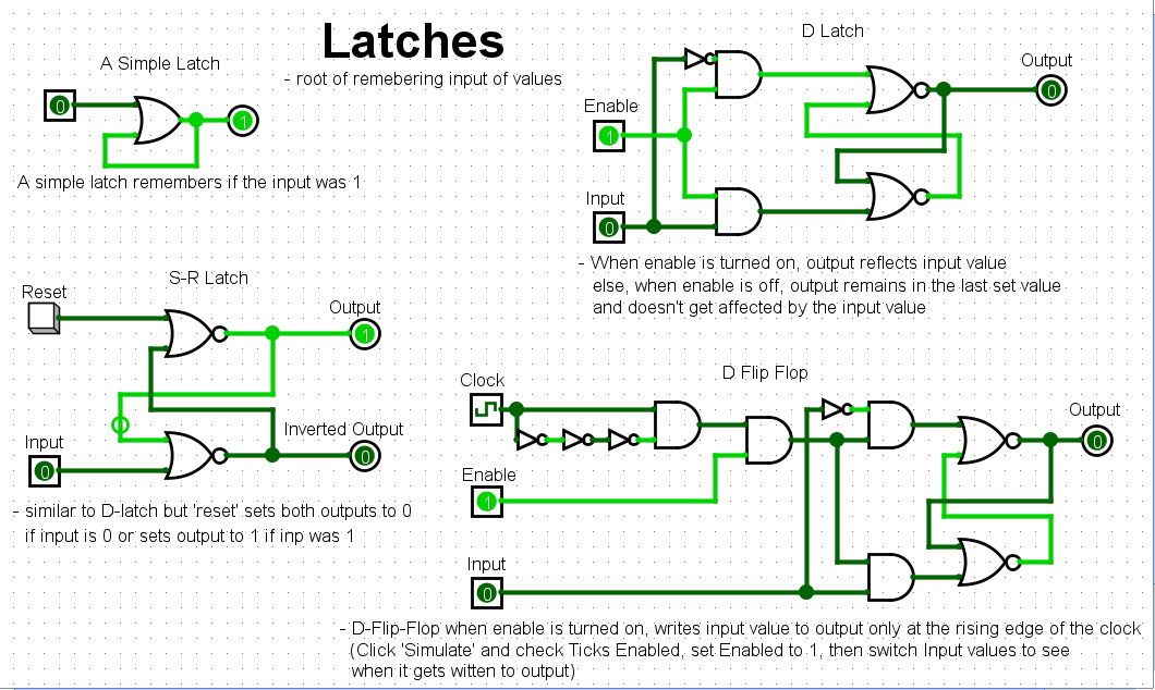
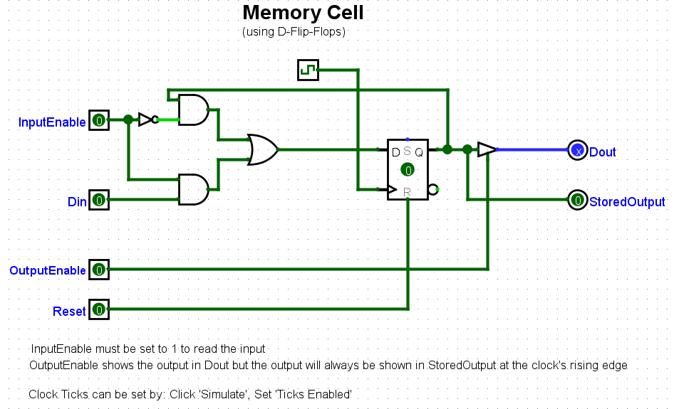
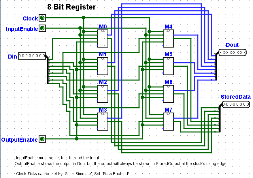
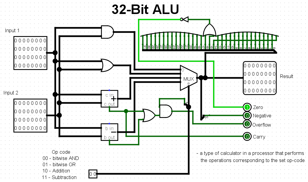
Some More Complex Circuits That I've Used As Part Of The 8-Bit CPU Project
The file for the below circuits can be viewed here
The file for the below circuits can be viewed here